Individual wires and cables
Wrap-around or self-laminating identifiers keep circuit information close to the conductor. Specify the actual outside diameter and the space available for overlap.
01 / Industry application
Label selection for individual wires, cable bundles and finished harnesses, considering diameter, jacket material, flexing and traceability.
02 / Where labels work
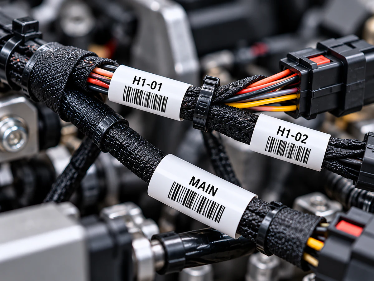
A harness identifier must remain associated with the correct circuit from assembly through installation and service. Available space changes between individual wires, connector branches and the finished bundle; one format rarely suits all three.
Wrap-around or self-laminating identifiers keep circuit information close to the conductor. Specify the actual outside diameter and the space available for overlap.
Flag formats can provide a larger reading area beside a branch or connector. Check clearance, snagging and orientation after routing.
Separate temporary inspection status from permanent assembly serial identification so a process label is not mistaken for the final identifier.
03 / Process and service
Evaluate bending during assembly, cable-jacket surface energy, oil from handling, abrasion at routing points and service heat. Moisture and UV become relevant for exposed cable runs.
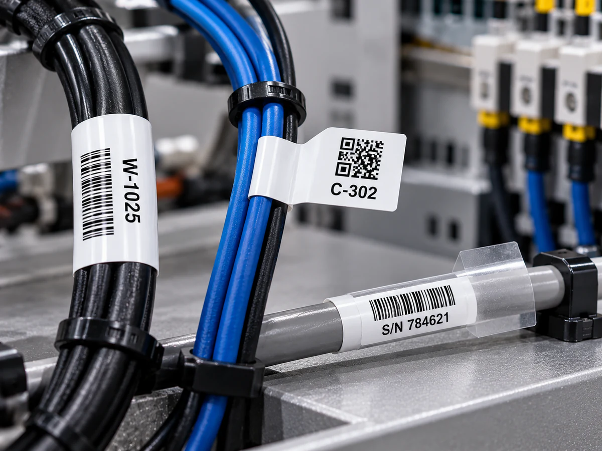
Wrap and flag formats provide different reading areas on cable assemblies.
05 / Material, adhesive and identification
Circuit text, connector references, barcode, QR, Data Matrix and assembly serialization can link branch identification to the build record. Confirm reading distance, code size and scanner access after installation.
Where the project requires it, review documented halogen-free and UL94 V-0 / VTM-0 construction options. Cord-label applications require their own applicable evaluation; equipment-label recognition must not be assumed to cover a wire marker.
Apply samples to representative jacket lots, allow the agreed dwell, route and flex the assembly, then check edge retention and code readability after the actual exposure sequence.
06 / Start a conversation
Share what you already know. We can work through the remaining details together.